

Blade Pitch Control: Why Helicopters Can’t Fly Without It While Multirotor Drones Get Away With Fixed Propellers
At a casual glance, helicopters and multirotor drones, such as quadcopters, look like variations on the same idea. A propeller spins fast, its twisted and curved blades push air downward, defying gravity at that moment, allowing the machine to stay in the air.
But closer examination highlights major technical differences. Helicopter relies on an elaborate mechanical contraption full of joints, bearings, and parts that spin fast while experiencing insane amounts of mechanical force. The multirotor drone relies on fixed propeller, making it much simpler mechanically and cheaper.

The obvious question is why. Why does a helicopter need blades that constantly change their angle of attack while spinning, even to remain stable, while a quadcopter flies just fine with rigid, fixed-pitch propellers?
To understand why, and what is actually going on, we need to talk about airflow, motion, and geometry.
Basics on the principles of flying
If you stand on a skateboard and throw a heavy object forward, you roll backward.
Air is a physical substance with mass, and it is heavy. If air is pushed downward, the reaction force on the object doing the pushing is upward.
When a solid surface (rotating rotor blade) moves through air, its geometry forces air to change direction and speed. Below the rotor, the air is being pushed downward, so it pushes upward on the rotor more strongly, which we call higher pressure. Above the rotor, the air is being pulled into the rotor disk and redirected, so it pushes on the rotor more weakly, which we call lower pressure.
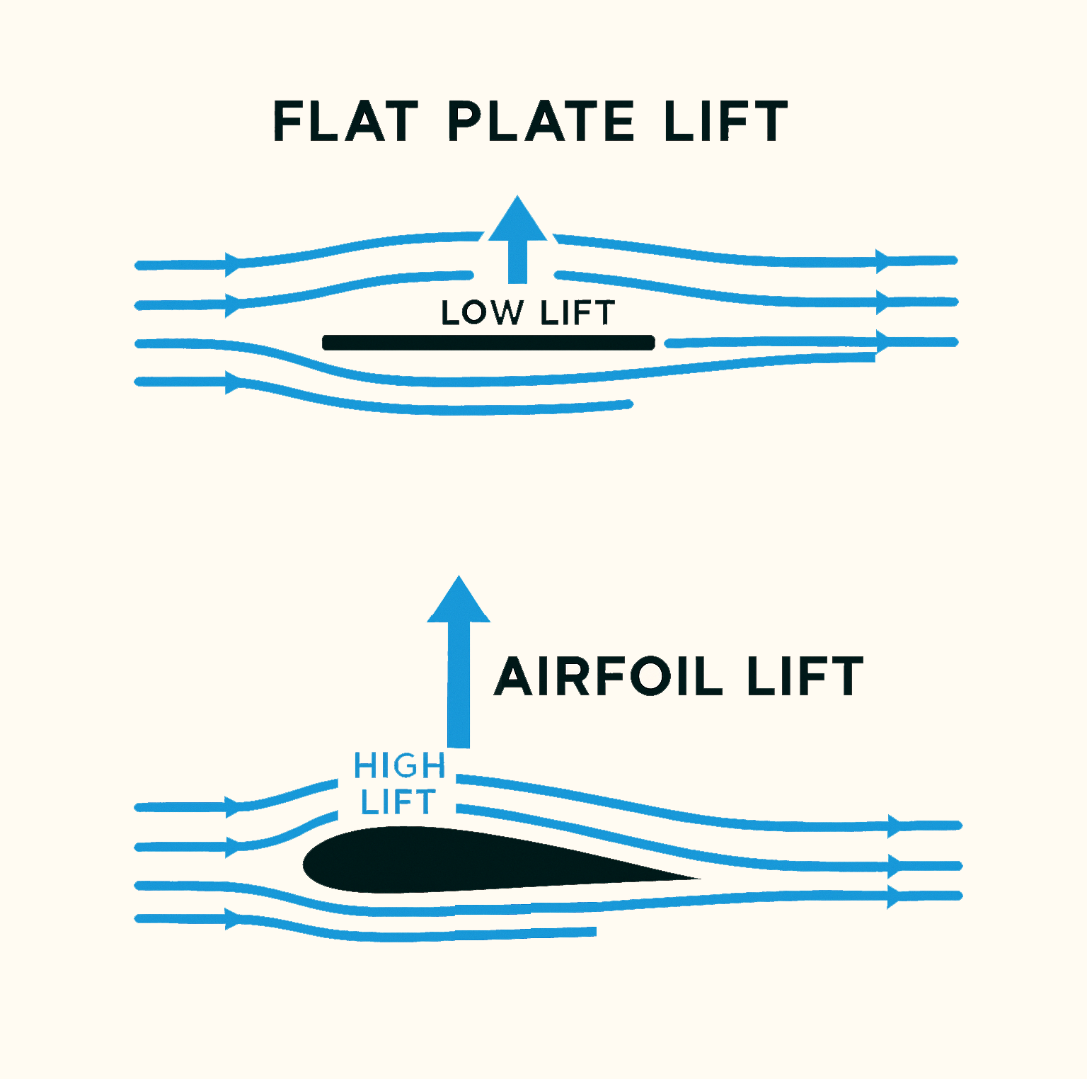
You can feel this effect by spinning a flat plate, a paddle, or a shovel above yourself (be careful with hard fast moving objects). If the plane of the spinning object is parallel to ground, a negligible net lift will be created. When the plane is slightly angled, you may feel some lift force.
A flat surface is highly inefficient as a rotor blade, so airfoil shapes are used to produce the pressure difference more efficiently, with less airflow resistance.
You may want to throw in a some math to shift from vague words into the area of precision.
Engineers often express the lift produced by a small section of a blade using an equation that separates these effects. Written in differential form, it is

Each symbol in this expression corresponds to a measurable physical quantity. The term dL is the small lift force produced by a short segment of the blade with length dr. The symbol ρ represents air density (approximately 1.225 kg/m³ at sea level). The symbol V represents the speed of the airflow relative to that blade segment. The symbol CL is a dimensionless coefficient that depends on the blade’s shape and its angle of attack. The symbol c is the chord length, which is the width of the blade measured from leading edge to trailing edge.
This formula shows that lift depends strongly on velocity. For a rotating blade, the dominant component of velocity comes from rotation. This rotational velocity exists regardless of whether the aircraft is hovering or moving forward.
Angle of attack — a key to the magic of flying
The symbol CL, which is a part of the formula for the lift, depends on the angle of attack. What is the angle of attack exactly?
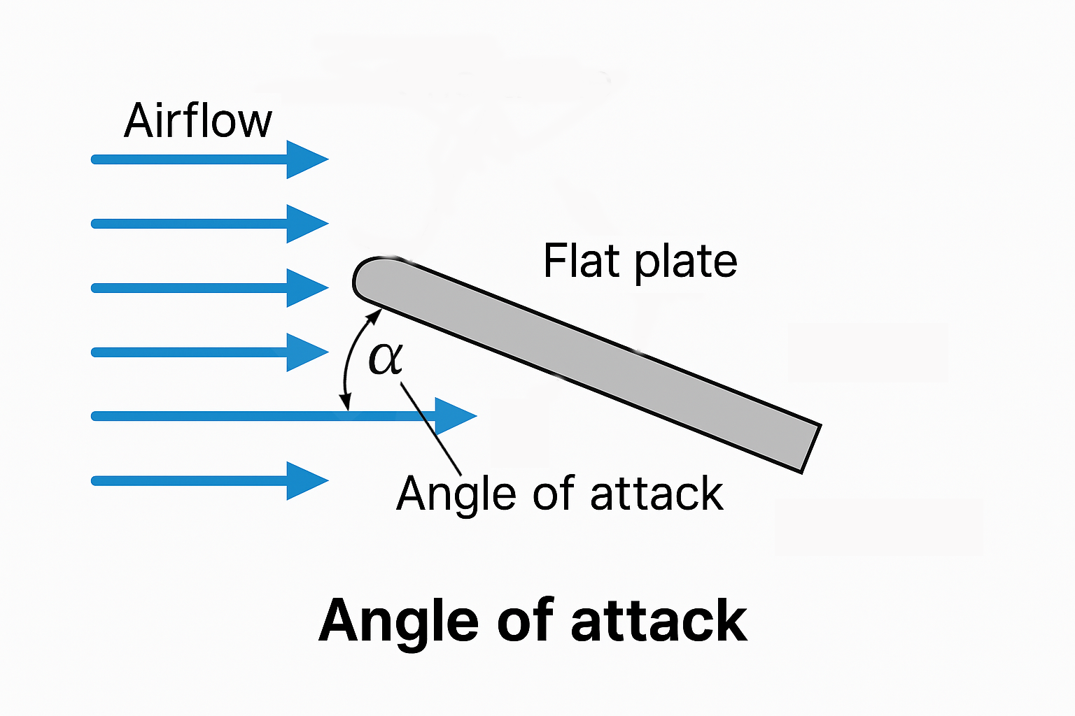
Angle of attack is simply the angle at which a moving surface meets the air that flows toward it.
It is the important variable that determines whether a rotor blade or airplane wing merely slips through air or actively pushes it downward to create higher lift.
To understand the angle of attack, imagine air as a stream of tiny particles moving past an object; if the object meets that stream edge-on, the particles are gently displaced and continue almost unchanged, but if the object is tilted slightly, those particles are forced to change direction, and that change in direction requires force.
The angle of attack describes exactly how much the surface is tilted relative to the incoming airflow, not relative to the ground, the horizon, or the aircraft itself.
When the angle is small, the surface deflects only a little air downward and produces little lift; when the angle increases, more air is redirected downward, increasing lift; when the angle becomes too large, the airflow can no longer follow the surface smoothly, the redirection becomes inefficient, and lift decreases.
In helicopters and quadcopters alike, the blades do not lift the aircraft by spinning alone, but by maintaining an appropriate angle of attack, ensuring that an upward reaction force is produced.
Why a helicopter needs blade pitch control, and quadcopter — does not
In a helicopter, several large blades act as a rotating wing, and as these blades move through the air they are set at an angle of attack relative to the oncoming airflow.
In ideally static environment (such an environment does not exist in reality) a fixed-pitch rotor could, in principle, produce vertical lift without additional corrections. However, if rotor tilts slightly, the lift force tilts with it. Once tilted, part of the lift force points sideways instead of upward, causing the aircraft to accelerate in that direction and tilt further. Without a way to actively control the direction of the lift force, the aircraft will not remain upright.
Helicopter controls the angle of attack for each of its rotor blades continuously (cycling) to avoid crashing in horizontal flight and manually by the pilot to control total lift amount and direction.
This can be clearly seen when a camera is fixed on the blade. On the video below the helicopter is in horizontal flight, and it automatically decreases the angle of attack (blade is rotated to “look downward” into ground) to decrease the lift generated by the blade that moves in the same direction as the direction of the flight. Without this automated cycling, the helicopter would become uncontrollable in horizontal flight.

At this point, it becomes clear that a helicopter requires a complex mechanical system to continuously control the angle of attack of its rotor blades, allowing it to control both the magnitude and the direction of the lift force produced by the rotating rotor disk and thereby maintain stable, controlled flight.
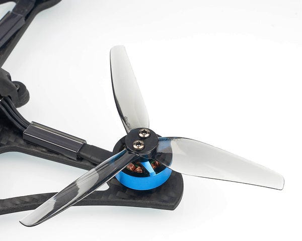
A quadcopter operates on exactly the same physical principle, but here is the catch: its rotor has a fixed blade pitch, meaning the blade position in relation to the quadcopter’s frame does not change. Design of a fixed pitch rotor is mechanically significantly simpler that helicopter’s rotor.
How does a quadcopter maintain stable, controlled flight if its rotors cannot actively change their blade pitch?
Instead of one large rotor with variable blade pitch a quadcopter uses four smaller rotors with fixed blade pitch, and lift is controlled by changing the rotational speed of each rotor. As the propellers spin faster, they move more air downward per unit time and increase the downward momentum of that air, which increases the upward force on the vehicle.
Each propeller produces a column of downward-moving air, and the combined effect of the four rotors provides enough upward force to balance weight during hover or to exceed it to gain altitude.
Directional control is achieved by creating deliberate differences in lift and torque between the rotors rather than by mechanically changing blade angles as in a traditional helicopter.
Because the quadcopter has multiple rotors placed at different positions on a rigid frame, changing the lift produced by one rotor or by a pair of rotors creates a controlled momentum in relation to the center of the mass.
This imbalance is executed continuously multiple times per second. Stability is achieved through rapid electronic feedback: onboard sensors measure the quadcopter’s orientation and motion, and a flight controller adjusts motor speeds many times per second to counteract disturbances before they grow catastrophically.
How helicopter and quadcopter turn in a spot?
Rotation in place, meaning turning left or right without moving sideways or forward, is achieved differently in helicopters and quadcopters. But in both cases it follows directly from conservation of angular momentum.
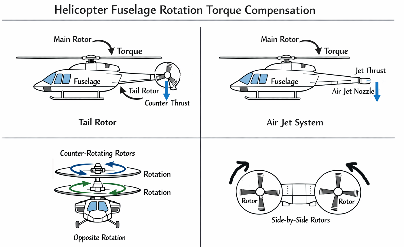
When a helicopter’s main rotor spins, it applies a counter rotational force to the helicopter’s body. This torque would cause the helicopter’s fuselage to rotate in the opposite direction of the rotor if nothing counteracted it. If this torque were not counteracted, the fuselage would rotate in the opposite direction of the rotor.
To prevent this, a counter-torque must be generated. In most helicopters this is achieved using a smaller auxiliary rotor mounted on a tail boom, which produces sideways thrust. Although the tail rotor is small and generates much less thrust than the main rotor, it is positioned far from the main rotor axis, so the resulting torque is sufficient to balance the main rotor torque. An alternative solution uses two large rotors rotating in opposite directions, typically arranged coaxially or in proximity, allowing their torques to cancel each other without the need for a tail rotor.
By decreasing or increasing the counter torque, helicopter can rotate its fuselage about its vertical axis.
A quadcopter solves the same problem by arranging its propellers to spin in opposite directions. Typically, two rotors spin clockwise and two spin counterclockwise. In steady hover, the twisting forces produced by these opposing rotations cancel each other out, resulting in no net torque on the frame.
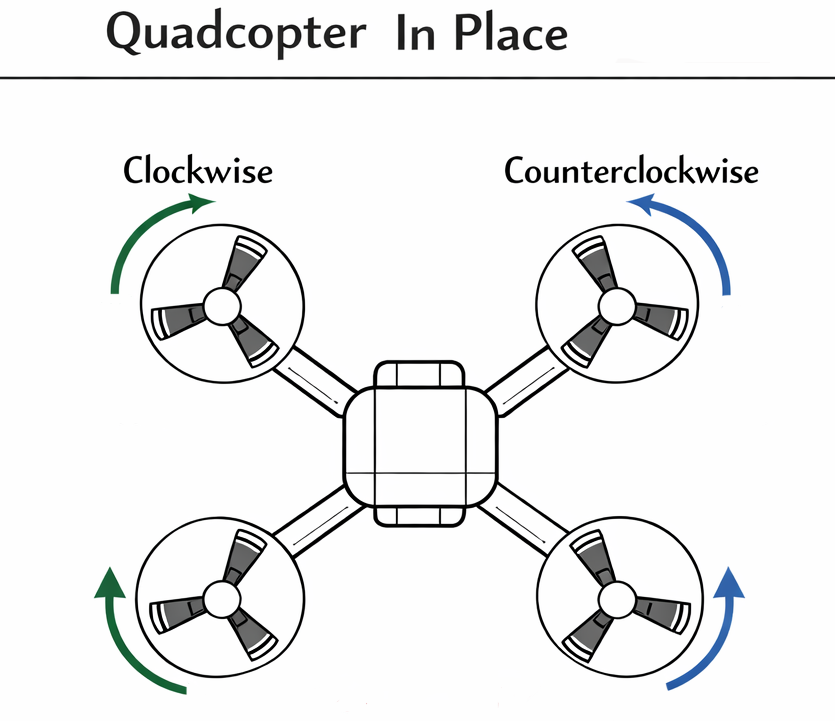
To rotate in place, the quadcopter slightly increases the speed of the rotors spinning in one direction while decreasing the speed of the rotors spinning in the opposite direction. The balance of rotational forces is disturbed, causing the entire aircraft to rotate around its vertical axis. As with all other aspects of quadcopter control, this adjustment is handled by rapid electronic feedback.